41
THERMAL ANALYSIS
Energy saving from a reduction pot
This paper puts forward the benefits of energy-saving in an aluminium reduction pot by minimising
heat loss through the use of a new thermal insulation lining, an insulated and sealed hood, composition
and thickness of the anode covering layer and installing an ‘irregular’ cathode with bevelled edges.
By Zhou Jianfei*, Marc Dupuis**, Yan Feiya*, Huang Jun* & Yi Xiaobing*
The key technologies applicable to primary
Heat output
maintained by reducing the heat
aluminium production are low-
1. Heat dissipation at pot top
dissipated from the pot and balancing the
temperature reduction, increasing the
- internal
cause:
cell
operating
heat input by reducing the voltage across
current,
on-line
measurement of
temperature (Topr)
the pot.
superheat,
Three-variable
control
- External cause: material and thickness
technology, anode slotting, bevelled
of anode covering materials, flue gas
Lowering voltage
cathode blocks, thermal insulation of pot
velocity and degree of sealing of pot
About half of the total power input of a
hoods, drainable cathodes and the
hood.
pot is used for electrolysis and half is lost
application of new lining designs and
2. Heat dissipation at pot side
through heat dissipation. Thus the focus
materials. These are being studied and
- internal cause: Tsuper heat
on achieving a lowering of pot voltage is
developed in China with the aim of raising
- External cause: bath level, metal level,
to reduce the heat lost from the pot. The
aluminium reduction technology to an
pot lining design.
optimum thickness of the side profile
advanced level.
3. Heat dissipation at pot bottom
ledge formed in the bath is a core factor
The consumption of energy and raw
- internal
cause:
cell
operating
in lowering the voltage.
materials for aluminium reduction has
temperature (Topr)
Too thick or too thin a ledge will have a
been high recently especially in regards to
- External cause: material and thickness
negative effect on the pot stability during
power consumption. Aluminium reduction
of cathode lining
production, affecting the voltage required
costs must be lowered.
and the current efficiency
(CE) and
The most efficient method to achieve
The objective is to minimise the voltage
possibly resulting in leakage from the pot.
this is to lower the consumption of the DC
drop across the cell by a combination of
Therefore, the distribution of heat
current used for electrolysis by increasing
adjusting the heat input, mainly by
dissipation and the formation of an
the current efficiency (CE) and reducing
adjusting the voltage drop across the cell
optimum thickness of the side ledge are
pot voltage.
between the anode and cathode (ACD).
key to pot design and has led to a new
The pot energy balance has been
The heat generated during electrolysis
thermal insulating lining being developed.
summarized by Warren Haupin[1] as:
arises from the Joule heat produced by the
current passing through the bath between
Heat dissipation: Pot top
Heat input
the anode and the cathode.
As the heat lost from the top of the pot
1.
Current (variable)
Stable production is maintained by
accounts for about half of the total heat
2.
Voltage
ensuring a dynamic balance of heat lost by
loss the focus on lowering heat loss is in
2.1
Anode (constant)
the pot and heat input by the Joule effect
this area. For a conventional pot, the heat
2.2
Cathode (constant)
during operation.
lost from the pot top equates to 1.0V to
2.3
ACD (Anode Cathode Distance)
If the Joule heat generated is insufficient
1.2V (the figure is expressed in volts since
2.3.1
Bubble voltage drop (variable)
to balance the heat output, the pot
Topr = heat loss in kW / Cell current in kA)
2.3.2
Bath voltage drop - ACD,
gradually cools, and the process can stop
and the pot voltage is required to be
bath ratio (variable)
and the pot freeze.
above
4.16V. However, based on the
2.3.3
Back-EMF (constant)
The energy balance of a pot can be
statistics of the pots operating with
Area
Heat
Heat
Heat
Area
Heat
Heat
Heat
Dissipation Area
Dissipation
Dissipation
(%)
Dissipation Area
Dissipation
Dissipation
(%)
(kW)
(V)
(kW)
(V)
Anode area
Pot hood
Pot side
112.8
0.348
18.4
Anode area
Pot hood
Pot side
97.1
0.299
18.1
cover plate
cover plate
Pot rim plate
15.5
0.047
2.5
Pot rim plate
21.0
0.064
3.5
Pot end
Pot end
cover plate
15.0
0.046
2.4
cover plate
18.3
0.050
2.7
Sub-total
143.2
0.439
23.4
Sub-total
134.4
0.412
22.2
Pot
Pot top
43.4
0.133
7.1
Pot
Pot top
67.1
0.206
11.1
superstructure
superstructure
Anode
Anode
guide bar
7.4
0.023
1.2
guide bar
6.9
0.021
1.1
Fume
181.5
0.557
29.7
Fume
111.5
0.342
18.5
Sub total
232.3
0.713
38.0
Sub total
185.5
0.569
30.7
Total
375.5
1.152
61.4
Total
319.8
0.981
52.8
Table 1 Distribution of heat loss from the anode area for a Type A conventional pot
Table 2 Distribution of heat loss from the anode area for a Type B pot
Aluminium International Today
March/April 2012
42 THERMAL ANALYSIS
Conventional Irregular
measures to improve the insulating
A pot operating at a lower voltage must
Cathode
properties at the middle and at the ends
maintain the thermal balance at a lower
Lining thickness (cm)
22
12
of the pot by increasing the thickness of
superheat. Thus the thickness of the pot
ACD (cm)
5.4
4.5
the covering layer to ensure uniformity of
lining must be matched to ensure
Superheat (°C)
8
7
the total thermal balance of the pot so as
sufficient heat dissipation and a uniform
Pot voltage (V)
4.17
3.85
to achieve a uniform and regular side
yet not excessive ledge thickness.
ledge within the pot.
Simulation software to show the energy
Table 3 Comparison of physical parameters of different
The thickness of the cover materials has
balance of an aluminium reduction pot
350kA pots
the greatest impact on heat dissipation at
was developed by GAMI and combines
the top of the pot. Taking a 350kA pot as
the thermal field simulation software
various currents, heat dissipation at the
an example, the covering layer was made
developed by Prof Marc Dupuis.
top is below 0.98V for pots with a voltage
up of equal parts of crushed bath and
The software aims at modelling various
lower than 3.9V. A lowering of the heat
alumina.
size pots as well as advanced reduction
dissipated from the top of the pot thus
technologies and process parameters and
has the greatest effect on lowering overall
Application of new pot hood
employs models for heat loss at the
heat loss and contributes the greater part
A new energy-saving sealed pot hood has
cathode, pot sides and pot ends as well as
to a lowering of pot voltage.
been designed. This is lined with a high
an anode model.
There is an important relationship
temperature fire resistant layer and with
These are combined through a three-in-
between heat dissipated from the top of
thermally insulating composites on both
one unifying method[3]. The models are
the cell and the pot voltage. Using data
the inner and outer surfaces of the hood.
based on data collected over a number of
from a 320kA pot in a Chinese smelter,
This insulating layer prevents the heat
years to verify optimum heat dissipation
this paper illustrates this relationship for
from the top of the pot escaping through
and correct ledge thickness.
two types of pot.
the sides of the hood and so reduces heat
The first type (Type A), is of conventional
loss from the pot. It was observed that the
Comparison of designs
design with a thinner cover material on the
external surface temperature of the pot
The results calculated for two different pot
anode and bath, a voltage of 4.16 to
hood was lowered by more than 10°C and
designs both operating at 350kA, one with
4.18V and heat dissipation of 1.153V in
the voltage reduced by 5 to 15mV using
a conventional lining and a flat bottom
the anode area. The total heat loss from
the new pot hood compared to a
cathode installed using conventional paste
the hood and superstructure of the pot in
conventional hood.
to seal the steel conduction bar into the
the anode area are summarised in Table 1.
cathode block. The second heat dissipation
The second type of pot (Type B), is a
Heat loss at pot sides and bottom
calculation was for a pot with a so called
redesigned version with a thicker layer of
The heat dissipated from the sides and
‘irregular’ cathode (a term adopted in China
covering material, a pot voltage of 3.8 to
bottom of the pot accounts for half of the
which first produced such cathodes in
3.85V and heat dissipation of 0.98V in the
total heat output. The degree of superheat
which the long edges of each carbon block
anode area, as summarised in Table 2.
of the electrolyte is directly related to heat
forming the base of the pot are bevelled -
dissipation, the principle of which is to
see Fig 2) and connected to the steel bus
Pot covering
maintain stable production at minimum
bars by sealing with molten cast iron poured
The composition and thickness of the pot
voltage by adjusting the superheat to
between the block and recesses bus bar.
covering layer regulates the thermal
ensure an energy balance. The design of
The physical parameters of the
balance which can be controlled by
the lining of the pot is indirectly related to
conventional pot with flat cathode are
adjusting the proportion of alumina in the
dissipation of heat. The purpose is to form
compared with those of the pot fitted with
mixture of alumina and crushed bath
a uniform but not excessive thickness of
the irregular cathode in Table 3.
electrolyte which makes up the covering
the ledge under a low superheat while
A comparison of heat dissipated at the
material as well as its thickness.
guaranteeing stable and effective
various parts of each pot is presented in
For large pots, it is necessary to take
production.
Table 4.
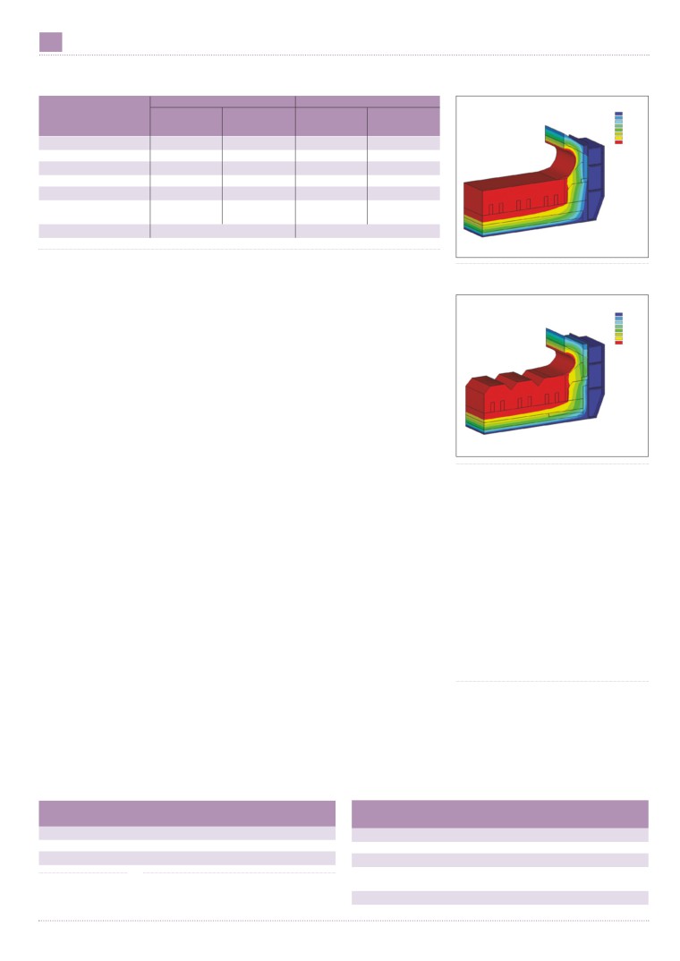
A comparison of the temperature
distribution
shows the
highest
Conventional
(mV)
New thermal
(mV)
temperature to be at the side steel plate of
lining structure
lining structure
a conventional lined pot reaching 301°C
Anode voltage drop
346
Anode voltage drop
347
while that for the pot fitted with the
Clamp voltage drop
15
Clamp voltage drop
15
irregular cathode was 230°C (Fig 2).
Guide rod voltage drop
26
Guide rod voltage drop
26
Comparing the profile ledge formed in
the two types of pots, the thickness of the
Explosive welding voltage drop
8
Explosive welding voltage drop
8
profile ledge at the sides of the
Anode stub welding drop
42
Anode stub welding drop
42
conventional pot was 10.9cm and that for
Voltage drop of iron/carbon joint
105
Voltage drop of iron/carbon joint
104
the redesigned pot 12.4cm and the ledge
Carbon block voltage drop
150
Carbon block voltage drop
151
thickness at the end of the pots was
Bath layer voltage drop
1502
Bath layer voltage drop
1228
16.7cm and 17.6cm respectively.
Bubble layer voltage drop
170
Bubble layer voltage drop
170
The ledge toe along the sides of the
Cathode voltage drop
284
Cathode voltage drop
229
pots showed a much greater difference at
Cathode steel bar voltage drop
109
Cathode steel bar voltage drop
106
18cm for the conventional and 30cm for
Cathode joint voltage drop
106
Cathode joint voltage drop
64
redesign and the ledge toe at the pot ends
Cathode carbon block voltage drop
69
Cathode carbon block voltage drop
59
was 13.8cm and 27cm respectively.
Counteraction electric potential
1672
Counteraction electric potential
1672
From a comparison of the distribution of
Voltage drop for busbar around pot
200
Voltage drop for busbar around pot
200
heat dissipation, the greatest heat loss for
Pot working voltage
4.174 (V)
Pot working voltage
3.846 (V)
the conventional pot is in the cathode
area, while that for the redesigned pot is
Table 4 Comparison of voltage distribution
in the anode area. The distribution of heat
March/April 2012
Aluminium International Today
44 THERMAL ANALYSIS
Conventional
New design
ANSYS 11.OSP1
Pot region
Heat loss
% Total
Heat loss
% Total
78.201
Plot No1
187.516
296.83
V
heat loss
V
Heat loss
406.145
515.459
624.773
Anode total
0.971
47.02
0.928
54.16
734.088
843.402
Cathode total
1.094
52.98
0.785
45.84
952.717
of which side
0.663
32.11
0.388
22.65
Rim plate
0.103
4.99
0.068
3.97
Bottom
0.163
7.90
0.143
8.33
Steel bar head
0.165
7.98
0.187
10.89
Total
2.065
1.713
Energy utilisation ratio
45.21%
50.25%
Cell temp 3D
Table 5 Comparison of heat dissipation distribution
Fig 1 Calculated temperature distribution for a
loss in the anode and cathode areas in a
Conclusions
conventional pot with flat cathode (pot end)
conventional lined pot are 47.02%, and
The methods to reduce energy
52.98% respectively and for the new
consumption through pot voltage
ANSYS 11.OSP1
76.616
design 54.16% and 45.84% respectively.
reduction with respect to heat dissipation
Plot No1
186.021
295.426
Thus the proportions of heat loss in the
are:
404.832
514.237
623.642
two types of pot are reversed (Table 5).
733.048
842.453
In the cathode area, the heat dissipation
- The thickness and composition of the
951.858
from the pot sides accounted for the
anode covering material;
greatest heat loss amounting to 32.11%
- The use of a new-design of thermal
of the total pot heat loss in the case of the
insulation including new types of material.
conventional pot and falling to 22.65% of
- Compared to a conventional pot, the
the total for the redesigned pot, but still
reduction in cell voltage is around 200-
remaining the major contributor to heat
450mV.
loss in the cathode area.
- The energy consumption per tonne
Cell temp 3D
aluminium is reduced by around 640-
Economic benefit
1440kWh/t at 93% current efficiency.
With the prerequisite that the efficiency of
- The annual reduction in energy
Fig 2 Calculated temperature distribution in a redesigned
the redesigned lining is 1-2% lower than
consumption of the pot line is typically
pot with irregular cathode (pot end)
that of the conventional lining, the
between 32x107 to 72x107kWh/y for a
China Guangxi Branch?’Comprehensive test report for
redesign can still save 900kWh/t of electric
pot line of capacity 500kt/y.
physics field of 320kA prebaked anode pot’, 2007.7.
energy consumption (Table 6).
- Savings in operation cost of a 500kt/y
[6] Aluminium Corp of China, Zhengzhou Research
smelter are in the range of RMB160M
Institute,
‘Comprehensive test and energy-saving
Comparison of heat loss
($25.3M) to 360M ($57.17M ) per annum
potential research report for 320kA pot’, 2008.6.
Table 7 shows that the distribution of
based on a power price of RMB0.5
[7] Aluminium Corp of China, Zhengzhou Research
heat loss between the cathode and the
($0.07)/kWh.
Institute,
‘Comprehensive test report for related
anode for the new thermal insulation pot
parameters measurement for 400kA pot’, 2008.3.
fitted with the irregular cathode is the
References
[8] Aluminium Corp of China, Zhengzhou Research
reverse of that seen in a conventional lined
[1] Warren Haupin, Halvor Kvande , ‘Thermodynamics
Institute,
‘Comprehensive test and energy-saving
pot with +54% of total heat lost from the
of Electrochemical Reduction of Alumina’, TMS Light
potential research report for 350 kA pot’, 2010.10.
anode in the new design compared with
Metals, 2000, 379-384.
[9] Gui Yang Aluminium and Magnesium Design and
43% in a conventional pot.
[2] Jayson Tessier, Carl Duchesne, Claude Gauthier,
Research Institute and Aluminium Corp of China,
The largest difference is for the heat lost
Gilles Dufour, ‘Image Analysis for Estimation of Anode
Guizhou Branch,
‘Comprehensive test report for
from the sides of the pots which decreases
Cover Material Composition’, TMS Light Metals,
physics field of 240 kA prebaked anode pot’, 2008.7.
from 35% for a conventional pot to 25%
2008, 293-298.
for the new design.
[3] Tian Yingpu,
‘Pot anode cathode distance
Contact
In the past two years the application of
composing model and process energy consumption’,
*Chalieco Gami, 2 Jinzhu Road, Jingyang,
the new insulation lining material has
Light Metals, 2011.3.
Guiyang, Guizhou, China 550081
become a focus for the aluminium
[4] Energy source science and engineering college of
Email jf_zhou@qq.com
industry. Ceramic fibres and compounds
Central South University and Aluminium Corp of
of silica, magnesium-aluminium type
China Guangxi Branch ’Comprehensive test report for
**GéniSim Inc, 3111 Alger St, Jonquière, QC,
thermal insulation materials are widely
physics field of 160 kA prebaked anode pot’, 2007.7.
Canada, G7S 2M9
used to insulate the inside and outside of
[5] Energy source science and engineering college of
Email marc.dupuis@genisim.com
the steel pot structure.
Central South University and Aluminium Corp of
Parameter
Conventional
New design
Conventional lining
New thermal
(%)
insulation lining %
Current efficiency
94%
93%
Anode area
43
>54
Daily aluminium production
2650kg
2622kg
Cathode area
57
<46
Direct current consumption
13231kWh/t
12323kWh/t
Lateral part of pot
35
<25
Pot rim plate
7
6
Table 6 (above)
Table 7 (right) Distribution of heat loss in a conventional
Bottom of pot
7
7
Comparison of economic
lined pot and the new thermal insulation lined pot with
Collector bar head
8
8
benefit
irregular cathode
March/April 2012
Aluminium International Today